A.W100.1 Arete logo name RGB(29,155,240) R TM SM Arete Consulting
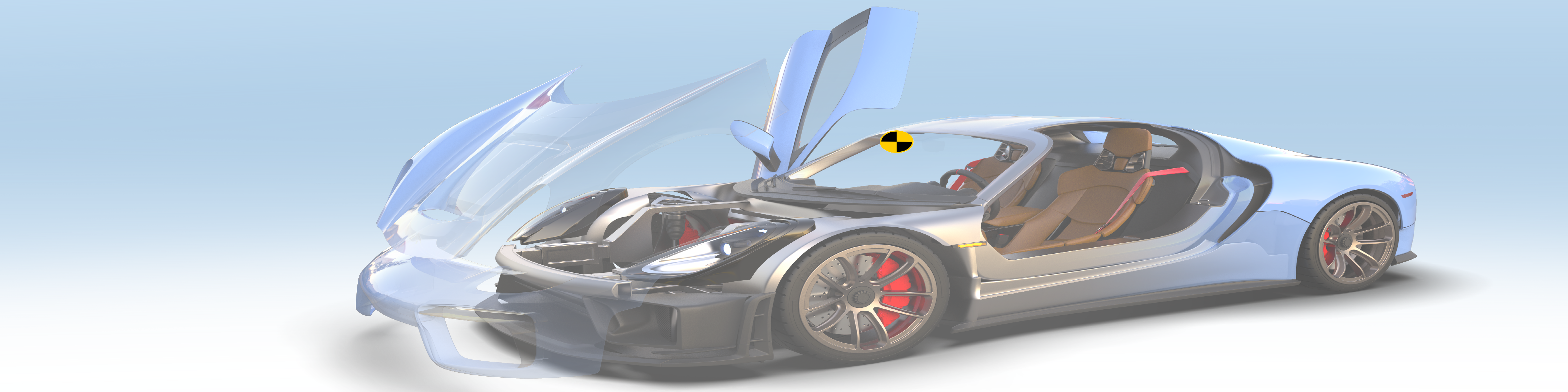
A.W114.1 AreteCutawayTransparentCar CTM US 49 CFR 571.103+ Glazing 70OPACITY

     Windshield Systems and Glazing

     Summaries of FMVSS 103, 104, and 205

Overview

Regardless of the nominal vehicle class, if a motor vehicle manufacturer voluntarily offers a full windshield and windshield-related equipment from a vehicle class with a passenger compartment (such as vehicle class “passenger car” that consequently creates a cabin “interior” with the capability of temperature and/or humidity differentials relative to the “exterior”), then FMVSS 103 and FMVSS 104 would consequently become requirements for due care, both from a regulatory and an engineering perspective.

Aside from the due care regulatory obligation based on a body of case law developed since the Highway Safety Act 1970 when NHTSA was established, it would arguably be a breach of engineering ethics to completely enclose a motor vehicle cabin with windshield and other glazing and then either (i) not offer, and/or (ii) not test such windshield-related systems.

An ethical motor vehicle manufacturer understands that voluntarily offering a full windshield and other glazing to completely enclose a vehicle cabin, necessarily entails providing windshield defrosting and defogging systems, as well as windshield wiping and washing systems, to ensure clear glazing requisite for driving visibility in case the glazing frosts, fogs, is wetted or dirtied, and also necessarily entails testing and verifying proper functionality of all the voluntarily offered equipment, that purport to operate in the manner and efficacy a driver expects of other vehicles with a windshield.

While such windshield-related systems may seem simple, they are actually quite complex, combining glazing engineering, thermal management engineering, electro-mechanical modules, and electronics, to name just a few competencies required. To properly design and develop such systems with robust D/PFMEA treatment, for various reasons it can be more practical, efficient, prudent, and regulatorily safe for a manufacturer to begin the process by thoroughly reviewing the plentiful SAE resources available on the topic of windshield defrosting and defogging, and wiping and washing systems.

49 CFR 571.103 Windshield Defrosting and Defogging Systems (FMVSS 103)

Test-Procedure TP-103-13, SAE J902_196408 and SAE J902A_196703 Passenger Car Windshield Demisting and Defrosting Systems, and defined Areas A and C of 49 CFR 571.104 Windshield Wiping and Washing Systems (FMVSS 104)

FMVSS 103 is relatively brief, as it references and relies upon SAE J902_196408, SAE J902A_196703, and defined Areas A and C of 49 CFR 571.104 Windshield Wiping and Washing Systems (FMVSS 104, see Arete summary) for most requirements.

  • NHTSA regulation 49 CFR § 571.5 Matter Incorporated By Reference (FMVSS 5) incorporates by reference over one hundred copyrighted standards, including SAE J902_196408 and SAE J902A_196703. Specifically, 49 CFR § 571.5(l)(29) incorporates by reference SAE J902_196408 “revised August 1964, into § 571.103”, and 49 CFR § 571.5(l)(30) incorporates by reference SAE J902A_196703 “revised March 1967 (Editorial change June 1967), into § 571.103” (PDF). Therefore, SAE J902_196408 and SAE J902A_196703 are incorporated by reference into U.S. federal law and consequently into all U.S. state laws.

FMVSS 103 applies to all vehicles with windshields, including passenger cars, multipurpose passenger vehicles, trucks, and buses. FMVSS 103 requires each vehicle (with a windshield and passenger compartment) to have a windshield defrosting and defogging system that meets the requirements of SAE J902_196408 Section 3, either by applying heat to the windshield or by dehumidifying the air inside the passenger compartment of the vehicle.

FMVSS 103 allows a heating system more appropriate for electric vehicles (EV), as described in S4.3(a)(1) and S4.3(b)(1). To harmonize FMVSS 103, FMVSS 104, SAE J902 and SAE J902A incorporated by reference, Area A means the “entire windshield”, and Area C means the “critical area” that the driver’s “eyellipse” describes (see SAE J941_201003 Motor Vehicle Drivers Eye Locations).

Testing vehicle parts and systems according to the procedures specified in FMVSS 103, such as TP-103-13, TP-104-08, SAE J902, and SAE J902A, requires far greater capabilities than can likely be performed by a start-up motor vehicle manufacturer. For example, see General Testing Laboratories test-report number 103-GTL-06-005, for NHTSA FMVSS 103 test identification number TRTR-638564-2006-005.

While a start-up motor vehicle manufacturer can perform simpler aspects and preliminary tests, for various reasons it can be more practical, efficient, prudent, and regulatorily safe for a manufacturer to contract independent, accredited test laboratories to perform all technically complex compliance testing. Aside from the technical knowledge and years of successful testing experience, accredited test laboratories provide specified test methodology and procedures, supplies held to close tolerances, and specialized equipment required.

For example, including but not limited to:

  • 20+ technical terms and definitions particular to FMVSS 103, FMVSS 104, SAE J902, SAE J902A, and related.

  • Test equipment and instrumentation includes but is not limited to a flow-meter for measuring liquid water flow rate, anemometer for measuring air velocity, timing devices, temperature measuring devices including thermometers and thermocouples, chassis dynamometer used to simulate road load and Equation 1 to determine vehicle air resistance horsepower.

  • Test chamber of refrigeration/freezer design and capability sufficiently large to contain chassis dynamometer, one or more motor vehicles, with provision for circulating freezing cold air at the specified temperature, velocity, and chamber exchange rate, and for auxiliary power supply for blower motor.

  • Throttle setting and control device, with engine/motor tachometer integrated with chassis dynamometer and electronic test instrumentation.

  • Stainless steel spray-gun for applying liquid water to the windshield with the following characteristics: 1.7 mm (0.070 in) nozzle size diameter, 345 kPa (50 psig) operating spray-gun gage pressure, and 0.0056 m3/s ±0.0004 m3/s (12 ft3/min ±1 ft3/min) airflow rate.

  • Test Condition: Test chamber shall have been maintained at or below the specified test temperature for not less than 24 hours preceding the vehicle soak period, and then the vehicle shall stand inoperative at the specified test temperature to soak for a period of not less than 10 hours at soak temperature -18 °C (0 °F) maximum.

  • Following the vehicle soak period, a test coating of ice shall be formed on the outer surface of the windshield as follows: With specified ambient temperature, the windshield shall be sprayed with an average of 0.046 mL of water/cm2 ±0.005 mL of water/cm2 (0.010 oz of water/in2 ±0.0001 oz of water/in2) of glazing area applied by means of the specified spray-gun with 345 kPa ±34.5kPa (50 psig ±5 psig) air pressure at the spray-gun while spraying to form an even test coating of ice over the entire glazing surface. The spray-gun nozzle (adjusted to full fan pattern and maximum flow) is held perpendicular to and 200-250 mm (8-10 in) from the glazing, stroked back and forth evenly in horizontal overlapping layers until the specified quantity of liquid is applied. Upon completion of the icing process, an additional soak period of not less than 30 minutes, and not more than 40 minutes, shall have elapsed before start of the test.

  • Test conditions are to be maintained throughout the duration of the test, however, the temperature at the thermocouple above the most forward point of the vehicle at the centerline of the vehicle and at the height of the center of the windshield area, shall not exceed -15 °C (5 °F).

  • At the completion of the test, the defrosted pattern shall be recorded by SAE J902 specified means, Table 1, and Figures 2, 3, and 4. Tests shall be run twice and averaged.

49 CFR 571.104 Windshield Wiping and Washing Systems (FMVSS 104)

Test-Procedure TP-104-08, SAE J903A_196605 Passenger Car Windshield Wiper Systems, SAE J941_196511 Passenger Car Driver’s Eye Range, and SAE J942_196511 Passenger Car Windshield Washer Systems

FMVSS 104 is relatively brief, as it references and relies upon SAE J903A_196605, SAE J941_196511, and SAE J942_196511 for most requirements, and mentions related Standard SAE J903.

  • NHTSA regulation 49 CFR § 571.5 Matter Incorporated By Reference (FMVSS 5) incorporates by reference over one hundred copyrighted standards, including SAE J903A_196605, SAE J941_196511, and SAE J942_196511. Specifically, 49 CFR § 571.5(l)(31) incorporates by reference SAE J903A_196605 “revised May 1966, into § 571.104”, 49 CFR § 571.5(l)(33) incorporates by reference SAE J941_196511 “approved November 1965, into § 571.104”, and 49 CFR § 571.5(l)(35) incorporates by reference SAE J941_196511 “approved November 1965, into § 571.104” (PDF). Therefore, SAE J903A_196605, SAE J941_196511, and SAE J942_196511 are incorporated by reference into U.S. federal law and consequently into all U.S. state laws.

FMVSS 104 applies to all vehicles with windshields, including passenger cars, multipurpose passenger vehicles, trucks, and buses. FMVSS 104 requires each vehicle (with a windshield and passenger compartment) to have a power-driven windshield wiping system that meets the requirements of SAE J903A, and to have a windshield washing system that meets the requirements of SAE J942.

To harmonize FMVSS 103, FMVSS 104, SAE J902 and SAE J902A incorporated by reference, Area A means the “entire windshield”, and Area C means the “critical area” that the driver’s “eyellipse” describes (see SAE J941_201003 Motor Vehicle Drivers Eye Locations).

To harmonize FMVSS 104, SAE J903A, SAE J941, and SAE J942 incorporated by reference, the term “seating reference point” is substituted for the terms manikin H point, manikin H point with seat in rearmost position, and H point wherever any of these terms appear in any SAE Standard or SAE Recommended Practice referred to in FMVSS 104.

Testing vehicle parts and systems according to the procedures specified in FMVSS 104, such as TP-104-08, SAE J903A, SAE J941, and SAE J942, requires far greater capabilities than can likely be performed by a start-up motor vehicle manufacturer. For example, see General Testing Laboratories test-report number 104-GTL-16-001, for NHTSA FMVSS 104 test identification number TRTR-644845-2016-001.

While a start-up motor vehicle manufacturer can perform simpler aspects and preliminary tests, for various reasons it can be more practical, efficient, prudent, and regulatorily safe for a manufacturer to contract independent, accredited test laboratories to perform all technically complex compliance testing. Aside from the technical knowledge and years of successful testing experience, accredited test laboratories provide specified test methodology and procedures, supplies held to close tolerances, and specialized equipment required.

For example, including but not limited to:

  • 70+ technical terms and definitions particular to FMVSS 104, SAE J903, SAE J903A, SAE J941, SAE J942, and related.

  • Test equipment includes but is not limited to: test-buck/vehicles capable of maintaining throughout the test the proper relationship of the glazing surface and the windshield wiping system components designed by the vehicle manufacturer, transparent heavy gage plastic sheet such as clear acetate or equivalent, power source to supply to the wiper motor the nominal power expected by the vehicle manufacturer under the specified test conditions in any of the test procedure paragraphs, spray equipment such as nozzles to apply water to glazing surface in accordance with the specified test procedures and test conditions, water softener where required to supply water in accordance with specified mineral content, and cleanser of a nonabrasive type.

  • Various test instrumentation, such as a flow-meter for measuring liquid water flow rate, anemometer for measuring air velocity, timing devices, and temperature measuring devices including thermometers and thermocouples, computer-based analytical tool capable of surface modeling full-scale windshield and wiper system layout, cycle counters for determining the number of cycles, hydraulic pressure gage, vacuum gage, and voltmeter.

  • Test chamber of heating/refrigeration/freezer design and capability sufficiently large to contain one or more test-bucks/vehicles, with provision for circulating hot, STP, and freezing cold air at the specified temperatures, velocity, and chamber exchange rate, and for auxiliary power supply for blower motor.

  • Test Condition: Test chamber shall have been maintained at the specified test temperature for not less than the specified time period preceding the test-buck/vehicle soak period, and then the test-buck/vehicle shall stand inoperative at the specified test temperature to soak for not less than the specified soak period at the specified soak temperature.

  • The vision areas are described by three specific areas on the exterior windshield glazing surface. The three areas are developed with the vehicle loaded to the manufacturer’s base design load and are identified in SAE J903A as Areas A, B, and C (see also SAE J903 Table 1). Each area has been established using the angles of Table 1 applied as shown in Figure 6. In the side views, the upper and lower boundary of the area is established by the intersection of two planes, which are seen as lines tangent to the upper and lower edges of the eyellipse, with the windshield glazing surface. The planes are fixed by angles above and below the XX line. In the plan view, the left and right boundary of the area is established by the intersection of two vertical planes tangent to the left and right edges of the eyellipse with the windshield glazing surface. The planes are fixed by angles to the left and right of the XX line. The areas used in determining the percentage of wiped area are those areas on the exterior glazing surface which are not within 25 mm (1 in) of the edge of the daylight opening (pillars, division bar, header, etc.). Using specified test procedures per Table 1 percentages, the percentage is the ratio of: the wiped area within the defined area, to the defined area. All work and calculations shall be performed based on the exterior of the windshield glazing surface. The design wipe pattern shall be shown plus the growth due to wet windshield and high-speed system operation (effective wipe pattern). This growth may be determined experimentally, or a predicted allowance for each direction of wipe may be utilized. Using 3-D vehicle coordinates, the windshield surface, daylight opening (DLO) curve(s), 95th percentile eyellipse per SAE J941, and developed areas A, B, and C (shown in Figure 7) shall be described on the exterior of the windshield glazing surface using the specified procedure and the angles from Table 1.
  • Each vehicle shall have a power-driven windshield wiping system that meets the requirements of SAE J903A (see also SAE J903):

    • Each windshield wiping system shall have at least two frequencies or speeds: (i) one frequency or speed shall be at least 45 cycles per minute regardless of engine load and engine speed, and (ii) regardless of engine speed and engine load, the highest and one lower frequency or speed shall differ by at least 15 cycles per minute. Such lower frequency or speed shall be at least 20 cycles per minute regardless of engine speed and engine load. Each vehicle windshield wiping system shall wipe the percentage of Areas A, B, and C of the windshield that (1) is specified in column 2 of the applicable table (80%, 94%, and 99%, respectively; See FMVSS 104 Tables I, II, and III for requirements applicable to vehicle width), and (2) is within the area bounded by a perimeter line on the glazing surface 25 millimeters from the edge of the DLO.

    • To demonstrate durability, the windshield wiping system shall remain functional after operating 1,500,000 cycles, 300,000 cycles at the high-frequency setting and 1,200,000 cycles at low-frequency setting, using dedicated test-buck/vehicle, specified test procedures, and test conditions, including but not limited to:
      • Wet operation water-on 5.5 minutes;
      • Dry operation water-off 0.5 minutes;
      • Park position 0.1 minute minimum to 1 minute maximum;
      • Water temperature 7-24 °C (45-75 °F);
      • Water nozzles located to provide equally distributed water flow on glazing surface at a rate no less than 820 cm3/min (50 in3/min);
      • Water hardness not to exceed 0.2 kg/m3 (12 grains/gal) minerals;
      • Ambient temperature 10-38 °C (50-100 °F).

    • To demonstrate strength, the windshield wiping system shall remain functional after withstanding the loads induced by stall, using dedicated test-buck/vehicle, specified test procedures, and test conditions, including but not limited to:
      • The wiper arms and blades shall be restrained from movement for 15 seconds at any position on the windshield;
      • Arm restraint may be applied anywhere along the arm and to each arm separately or both arms together;
      • Blade to be restrained along the entire length of the rubber blade element;
      • The wiper system shall be tested at each of the following two temperatures: -30 and 55 °C ±3 °C (-20 and 130 °F ±5 °F);
      • The wiper system shall also meet this requirement at the temperature (between listed limits) which corresponds to the highest output torque at the pivot.

    • To demonstrate temperature operational capability, the windshield wiping system shall be capable of operating between temperatures of -30 and 55 °C ±3 °C (-20 and 130 °F ±5 °F), using dedicated test-buck/vehicle, specified test procedures, and test conditions, including but not limited to:
      • (i) For the Hot Test procedure, the test-buck/vehicle and spray equipment are to be soaked in the test chamber at a temperature of 55 °C ±3 °C (130 °F ±5 °F) for 4 hours, and following this soak period and in the same temperature environment, the wiper system and spray equipment are to be turned on and operated for a period of 0.5 hour at maximum wiper speed control setting with water applied continuously as specified;
      • (ii) For the Cold Test procedure, the test-buck/vehicle is to be soaked in the test chamber at a temperature of -30 ±3 °C (-20 ±5 °F) for 4 hours, and following this soak period and in the same temperature environment, the wiper system is to be turned on and operated for a period of 0.5 hour at maximum wiper system speed control setting.

    • To demonstrate windlift resistance, the windshield wiper blade element shall continue to contact at least 98% of Area C, in each wiper travel direction, to meet the minimum requirements (equipped with new OEM blades) when subjected to relative air speeds equal to 80% of the vehicle’s maximum speed, but not exceeding 160 km/h (100 mph) while operating at maximum frequency, using dedicated test-buck/vehicle, specified test procedures, and test conditions, including but not limited to:
      • Water temperature 7-24 °C (45-75 °F);
      • Water nozzles located to provide equally distributed water flow on glazing surface at a rate no less than 820 cm3/min (50 in3/min);
      • Water hardness not to exceed 0.2 kg/m3 (12 grains/gal) minerals;
      • Ambient temperature 10-38 °C (50-100 °F), with relative air speed set to 0 km/h (0 mph) and system operating frequency set to maximum setting determine system cleared area as specified, and with relative air speed set equal to 80% of the vehicle’s maximum speed but not exceeding 160 km/h (100 mph) and system operating frequency set to maximum setting determine the system cleared area by noting any ballooning, scalloping, chatter, etc.

    • To demonstrate accessibility, the control of the wiper system should be positioned so that it is readily accessible to the driver. Controls should be in an area that does not restrict operator’s normal bodily movement or require diverting attention from any main visibility area.

    • To demonstrate wiper blade aging resistance, the windshield wiper blade element of the windshield wiper blade assembly shall withstand the specified ozone test, with an ASTM rating of 2, as defined in ASTM D1171 (current active version ASTM D1171-18 Standard Test Method for Rubber Deterioration - Surface Ozone Cracking Outdoors (Triangular Specimens)), using commercial ozone test cabinet, specified test procedures, and test conditions, including but not limited to:
      • The windshield wiper blade elements used for testing shall not exceed age of three months from the manufacturing date;
      • A 150 mm (6 in) specimen of the wiper blade element from the wiper blade assembly is to be installed in a suitable clamping fixture similar to that described in Method A of ASTM D518 Standard Test Method for Rubber Deterioration - Surface Cracking (withdrawn, and replaced by D1149, current active version ASTM D1149-18 Standard Test Methods for Rubber Deterioration - Cracking in an Ozone Controlled Environment);
      • Gage marks are applied that are 100 mm (4 in) apart;
      • Test specimens are then stretched, causing an extension of 15% between the gage marks;
      • The mounted specimens are then to be exposed for 48 hours in an ozone-free atmosphere;
      • Test specimens are to be placed in the ozone test chamber for a period of 72 hours;
      • The commercial ozone test cabinet is to be operated at a temperature of 38 °C ±3 °C (100 °F ±5 °F) and at a concentration of 50 pphm ±5 mPa partial ozone pressure.

    • To demonstrate chemical resistance, a section of the windshield wiper blade element, when placed in a 50% solution of either methyl or isopropyl alcohol for a period of 24 hours at 23 °C ±2 °C (73 °F ±4 °F), shall not exceed more than 2% weight change. Test method and weight change will be determined in accordance with ASTM D471 (current active version ASTM D471-16a Standard Test Method for Rubber Property - Effect of Liquids).
  • Each vehicle shall have a power-driven windshield washing system that meets the requirements of SAE J942:
    • To demonstrate washer system capability, the windshield washer system, in conjunction with the windshield wiper system, shall be capable of clearing, within 5 wiper cycles, 80% of the total wash area and 90% of the wash area included in Area C as defined in SAE J903A for passenger cars (see also SAE J903).

    • To demonstrate washer system strength, the windshield washer system shall be capable of withstanding the loads induced when either all nozzles are blocked or the system is frozen and tested in accordance with the specified test procedures. At the completion of the test, the system shall function.

    • To demonstrate washer system priming, on a non-primed or fully drained hose/nozzle system, washer fluid shall contact the target area and wipers shall begin cycling within 4 seconds from the time the washer control is activated.

    • To demonstrate temperature performance and exposure performance, including low-temperature exposure, high-temperature exposure, and operating range, after testing in accordance with the specified test procedures there must be no leakage or disconnection of the tubing and the windshield washer system must be functional and deliver a minimum of 75% of the original flow rate and deliver fluid to the target area of the glazing surface (i) after being subjected to a total of 6 freeze-thaw cycles with a freeze temperature of -30 °C (-20 °F), (ii) after exposure to a temperature of 91 °C (196 °F), and (iii) within a temperature range of -18 °C ±3 °C (0 °F ±5 °F) to 80 °C ±3 °C (176 °F ±5 °F).

    • To demonstrate durability, the windshield washer system must be functional and deliver a minimum of 75% of the original flow rate and deliver fluid to the target area of the glazing surface after operating 8,000 durability test cycles in an environmental chamber at 100 °C ±3 °C (212 °F ±5 °F) for 70 hours, in the sequence indicated in Table 1 (four tests of 2,000 cycles each at various temperatures ranging from -18 °C ±3 °C (0 °F ±5 °F) to 66 °C ±3 °C (151 °F ±5 °F)), using the low temperature washer solution when required. There must be no leakage or disconnection of the tubing.

    • To demonstrate windshield washer tubing performance, including ozone resistance, temperature aging resistance, and stress relaxation, after testing in accordance with the specified test procedures the tubing shall show no visual evidence of splitting or cracking, the reduction in elongation shall not be greater than 50% in the unexpanded portion of the specimen, there shall be no visual evidence of wax or other contaminants exuding from the tubing, and the tubing ID shall be no larger than 1.65 times the tubing original nominal ID.

    • To demonstrate chemical resistance, The windshield washer system shall not be adversely affected when operated with a 50% solution of methyl alcohol or isopropyl alcohol.

    • To demonstrate accessibility, the production intent in-vehicle control and the reservoir filler opening shall be positioned so that they are readily accessible.

49 CFR 571.205 Glazing Materials (FMVSS 205)

Test-Procedure is visual inspection of regulatory markings per standard ANSI/SAE Z26.1-1996 American National Standard for Safety Glazing Materials for Glazing Motor Vehicles and Motor Vehicle Equipment Operating on Land Highways - Safety Standard

FMVSS 205 is relatively brief, as it references and relies upon ANSI/SAE Z26.1-1996 for most requirements.

  • NHTSA regulation 49 CFR § 571.5 Matter Incorporated By Reference (FMVSS 5) incorporates by reference over one hundred copyrighted standards, including ANSI/SAE Z26.1-1996. Specifically, 49 CFR § 571.5(c)(4) incorporates by reference ANSI/SAE Z26.1-1996 “approved August 11, 1997, into § 571.205” (PDF). Therefore, ANSI/SAE Z26.1-1996 is incorporated by reference into U.S. federal law and consequently into all U.S. state laws.

ANSI/SAE Z26.1-1996 describes two main categories of glazing: in a location and at a height requisite for driving visibility, and not requisite for driving visibility.

FMVSS 205 requires a visual inspection of the glass in the various locations of the vehicle for tinting, shading, and approved material regulatory markings required for that location in the vehicle per standard ANSI/SAE Z26.1-1996.

ANSI/SAE Z26.1-1996 used here in whole or in part for purposes of criticism, comment, teaching, scholarship, and/or research, which qualify as Fair Use and which are recognized as not copyright infringement under U.S. law. For more information, see Terms of Use > Fair Use Notice.


NHTSA Test Procedures

Contact

Hello@AreteConsulting.org   in

A.W130.1 Flickr - Phil Varney - Great Smoky Mtns Natl Park - Newfound Gap Road

             Photo Phil Varney

Copyright © 2021-2026 Arete Consulting. All rights reserved.

Always hand-crafted, never AI-generated.

Site Map | Attributions | Privacy Notice | Disclaimers

Using the Website means you consent to the Terms of Use.

Webpage document code: A.W236.2